For several years now, my Marantz SR8500 A/V receiver has randomly refused to power on from standby, and occasionally kicks out of operation. I think it has something to do with the ambient temperature and humidity, which has been out of control this year in NYC.
Let’s see if we can fix it.
Background
My only datapoint to work from is a brief flash of the words “CHECK POW5” on the receiver’s display. I found a blog post that describes this as when the receiver goes into “protection mode” which can occur for multiple reasons.
Procedure
The service manual:
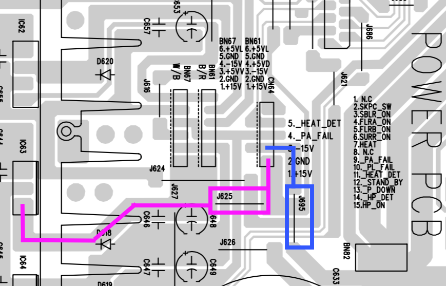
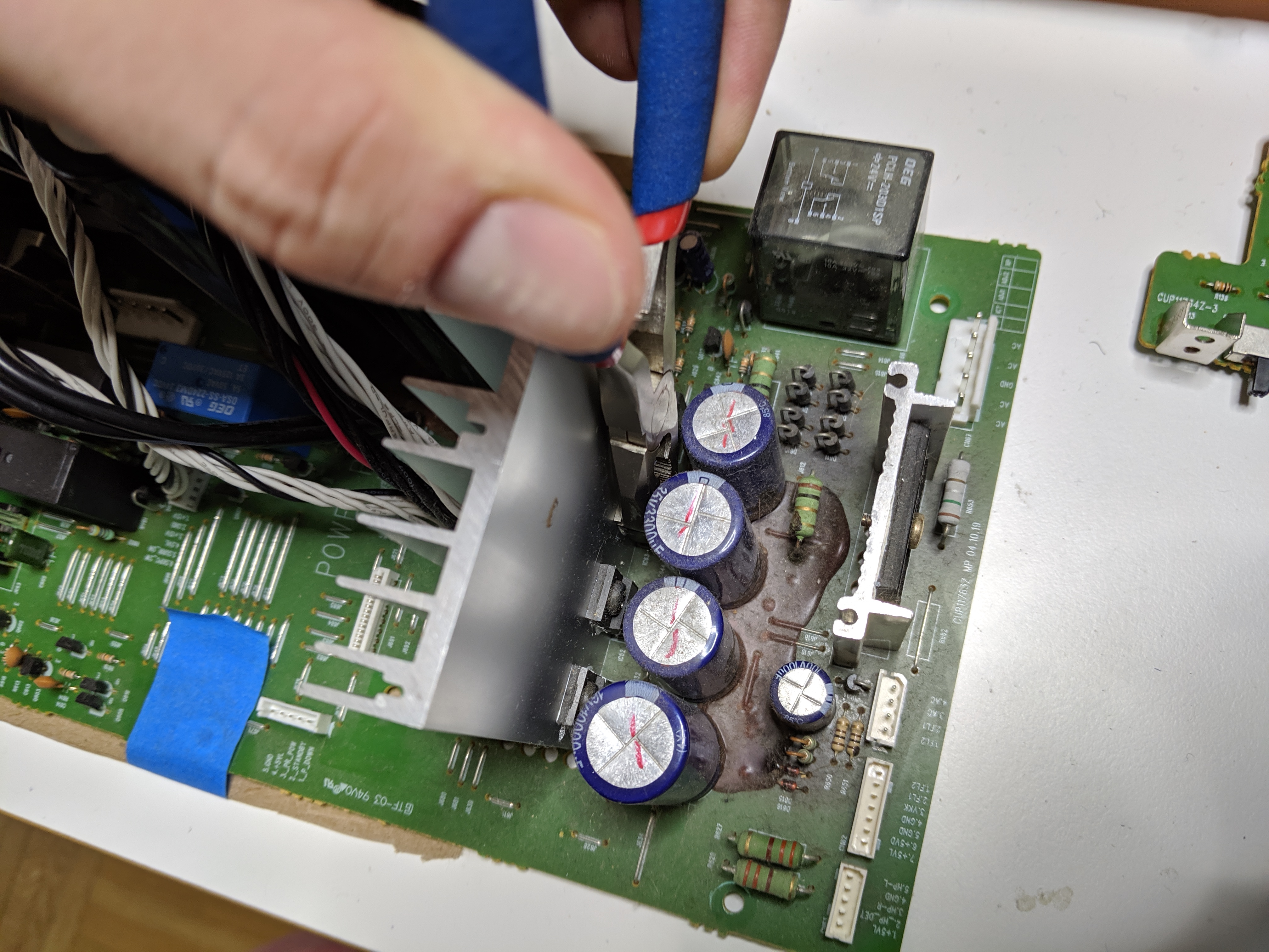
I’m looking at the 5v power rail first because that’s what the error message on the display is complaining about. There’s a 5v regulator (LDO) on the standby PCB and the first thing I noticed is a flat ribbon cable was resting against the LDO’s heatsink tab. There was some soot around the contact point, but the conductor within the ribbon cable potentially making electrical contact is listed as “N.C.” so I don’t think that’s a problem.
The schematic shows three 5v supplies: +5VL, +5VD and +5VV. They all come up and hold steady. I then look for a higher-voltage DC supply in case the 5v supply on other boards is generated locally. Sure enough, there are +15V and -15V supplies on the power PCB and I can see local 5v LDOs on several other boards. -15V comes up (down) as expected, +15v makes a lame attempt to hit +1v and sinks to nothing.
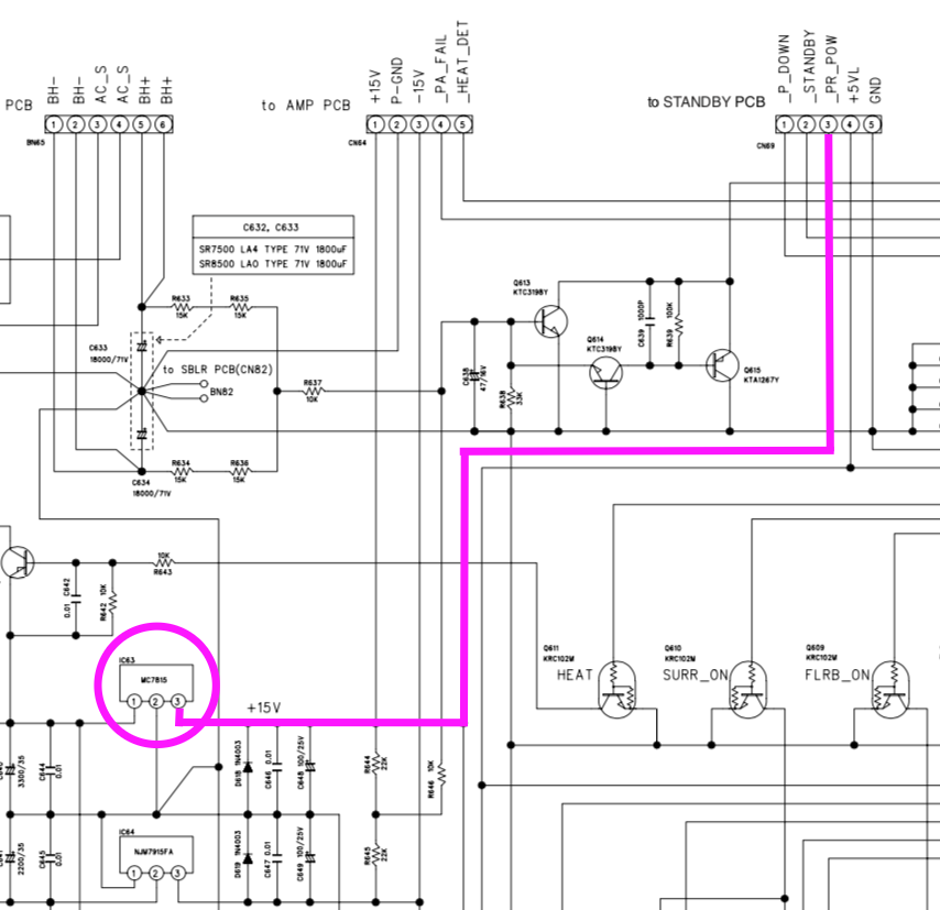
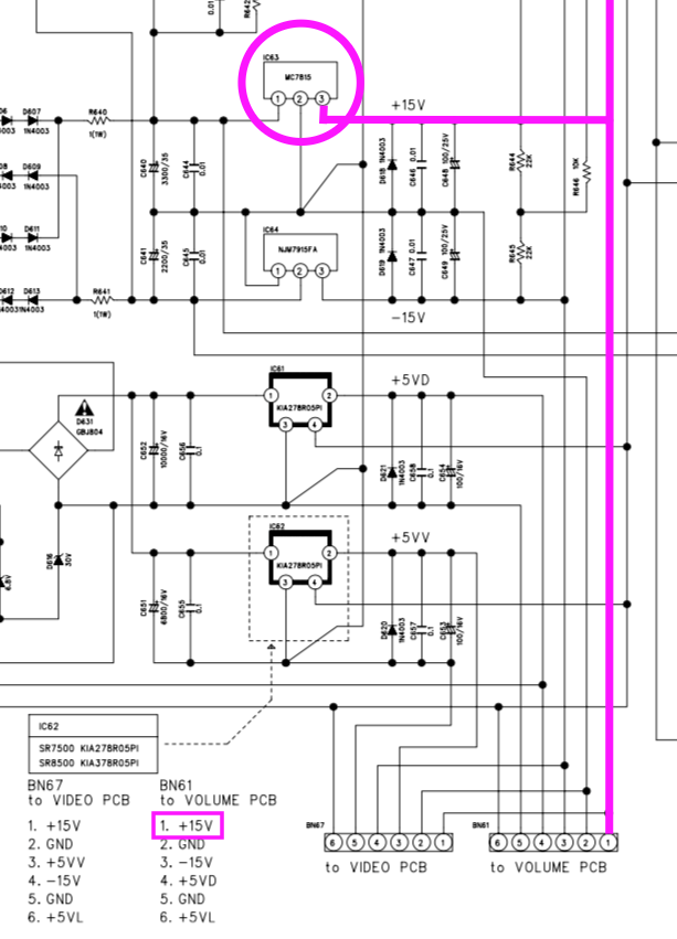

A check of the +15V network in the schematic shows no obvious barrier to hooking a bench supply to the system here, so let’s put +15v on the +15V supply and see what happens.
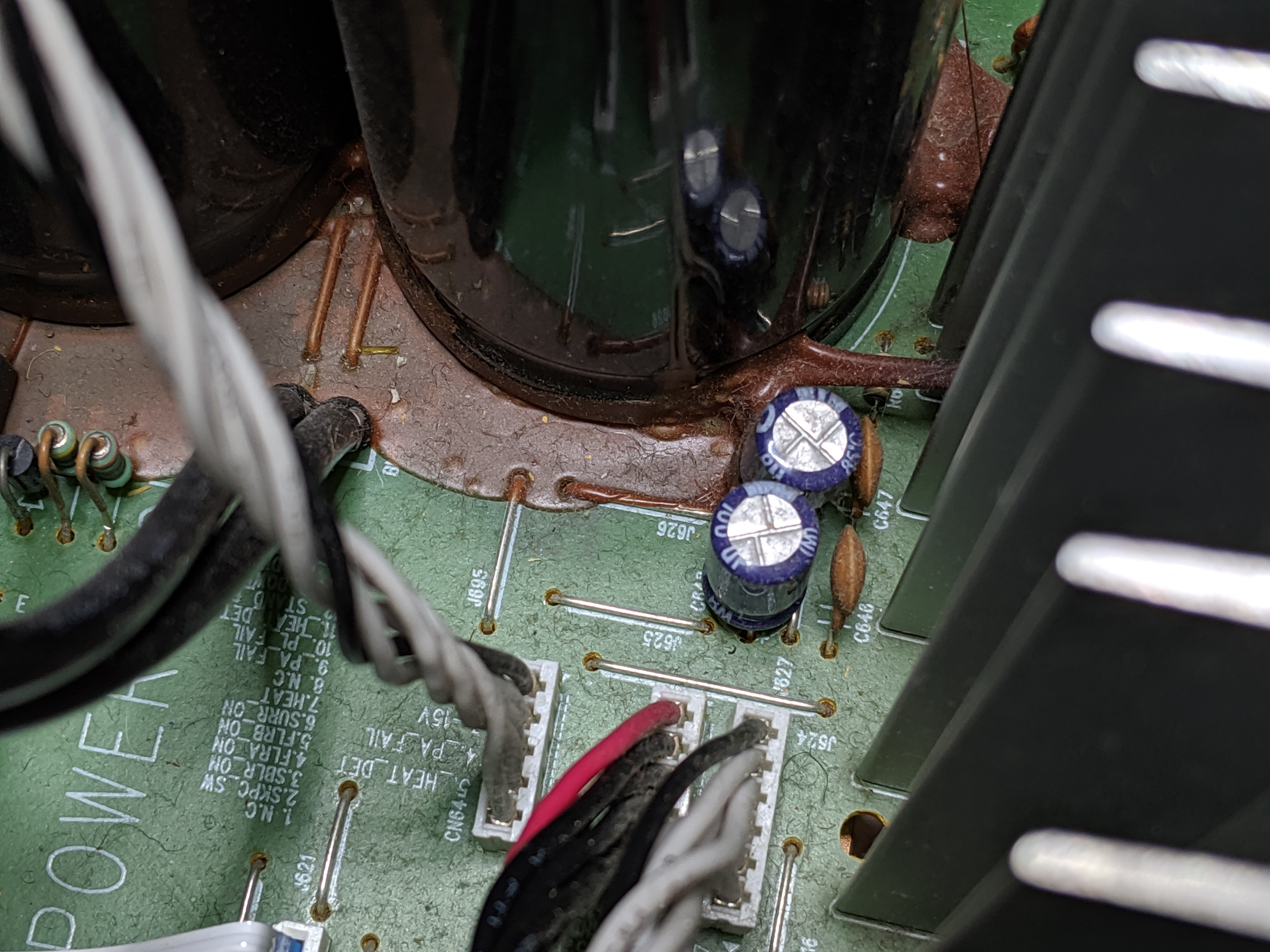
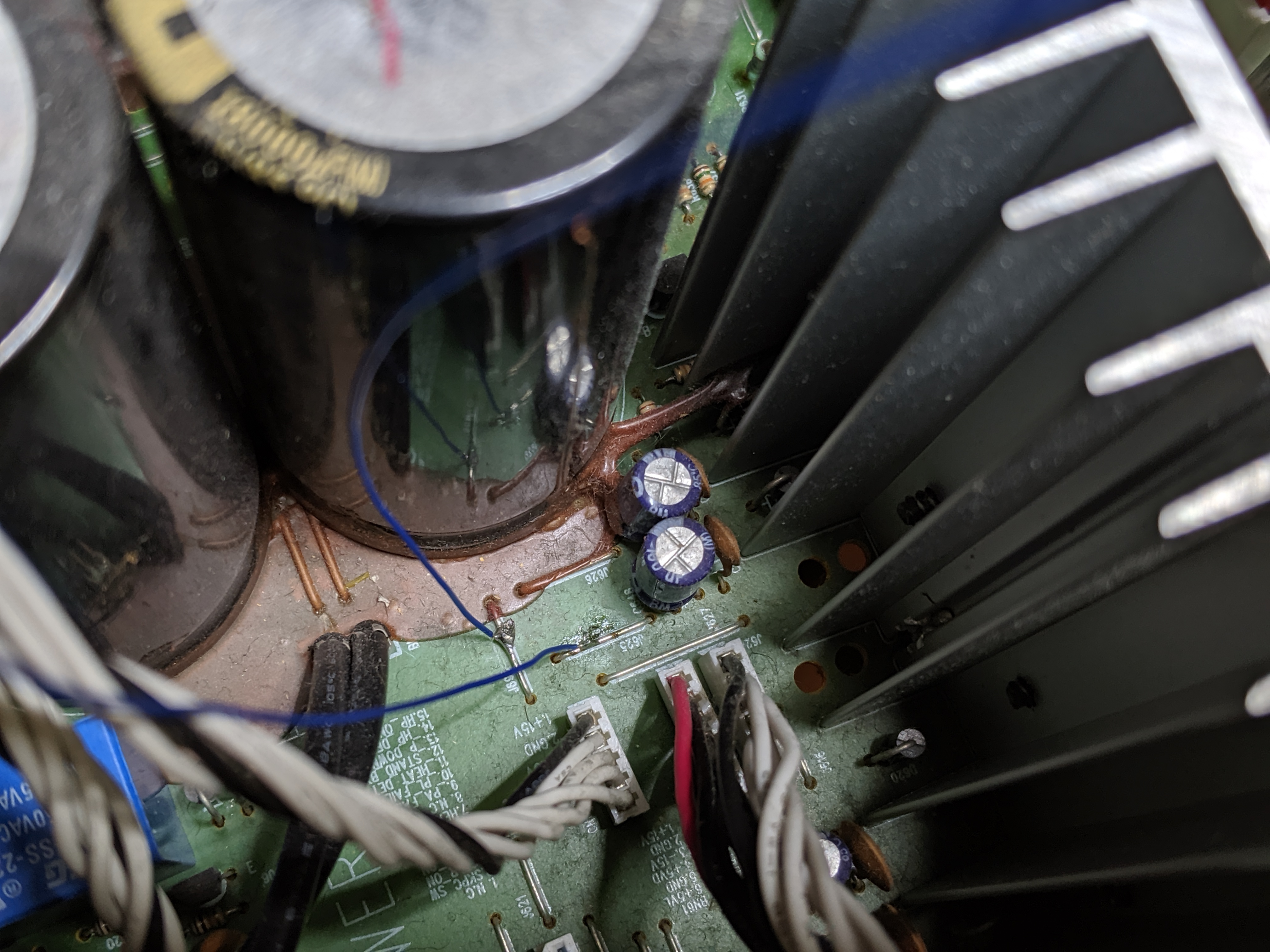
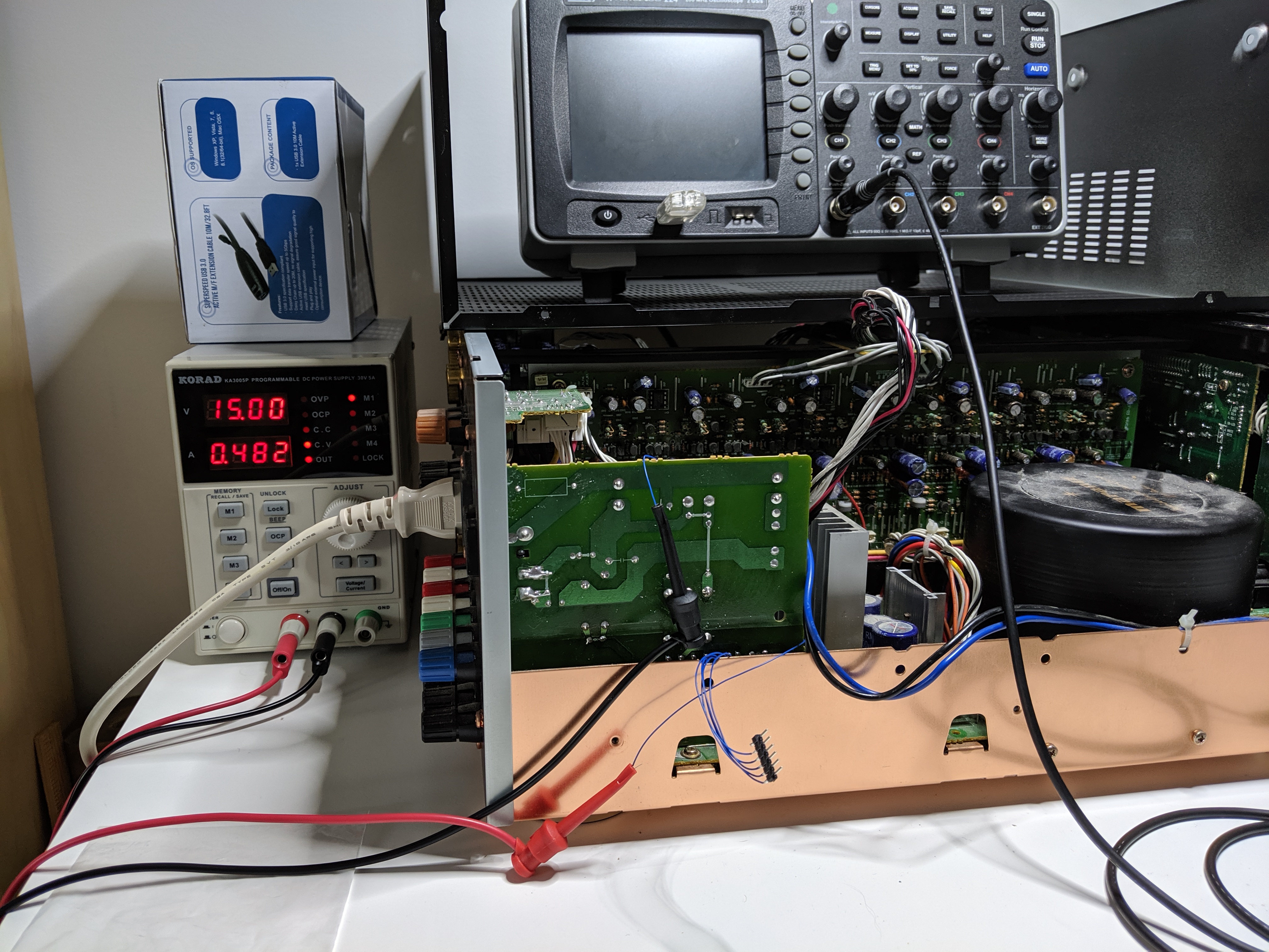
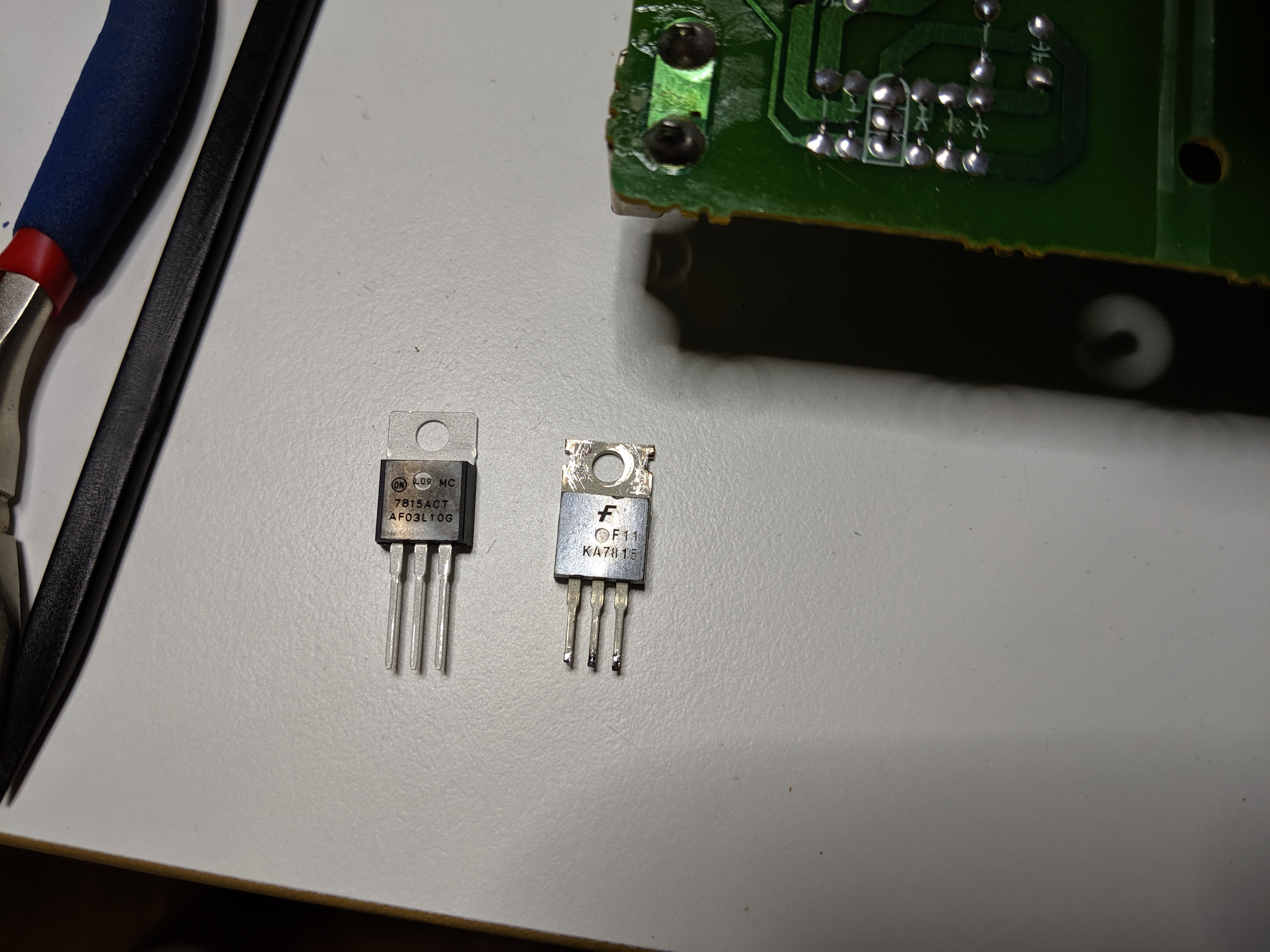
Aw yea. Cool, we’ll just replace IC63: an MC7815.
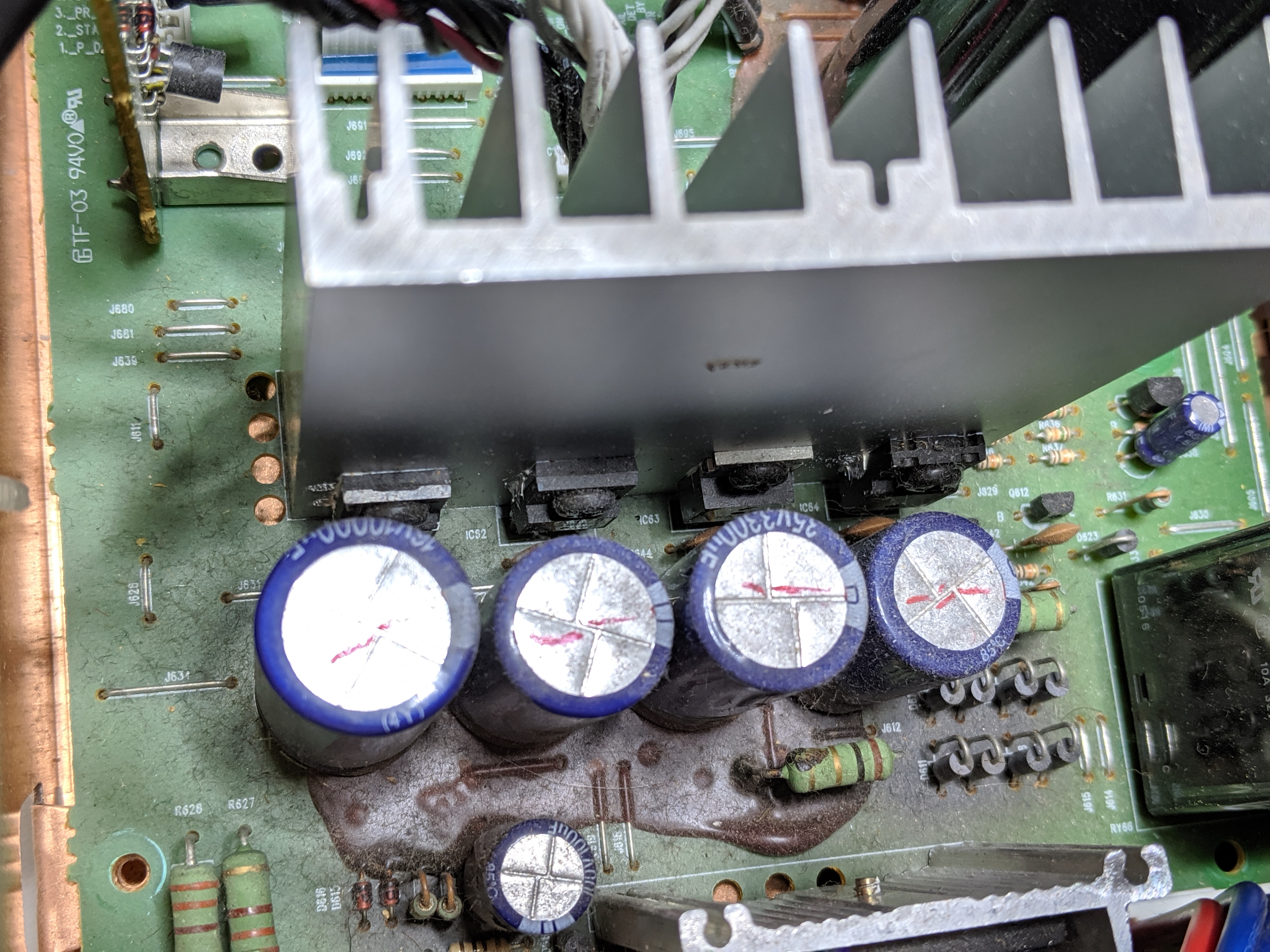

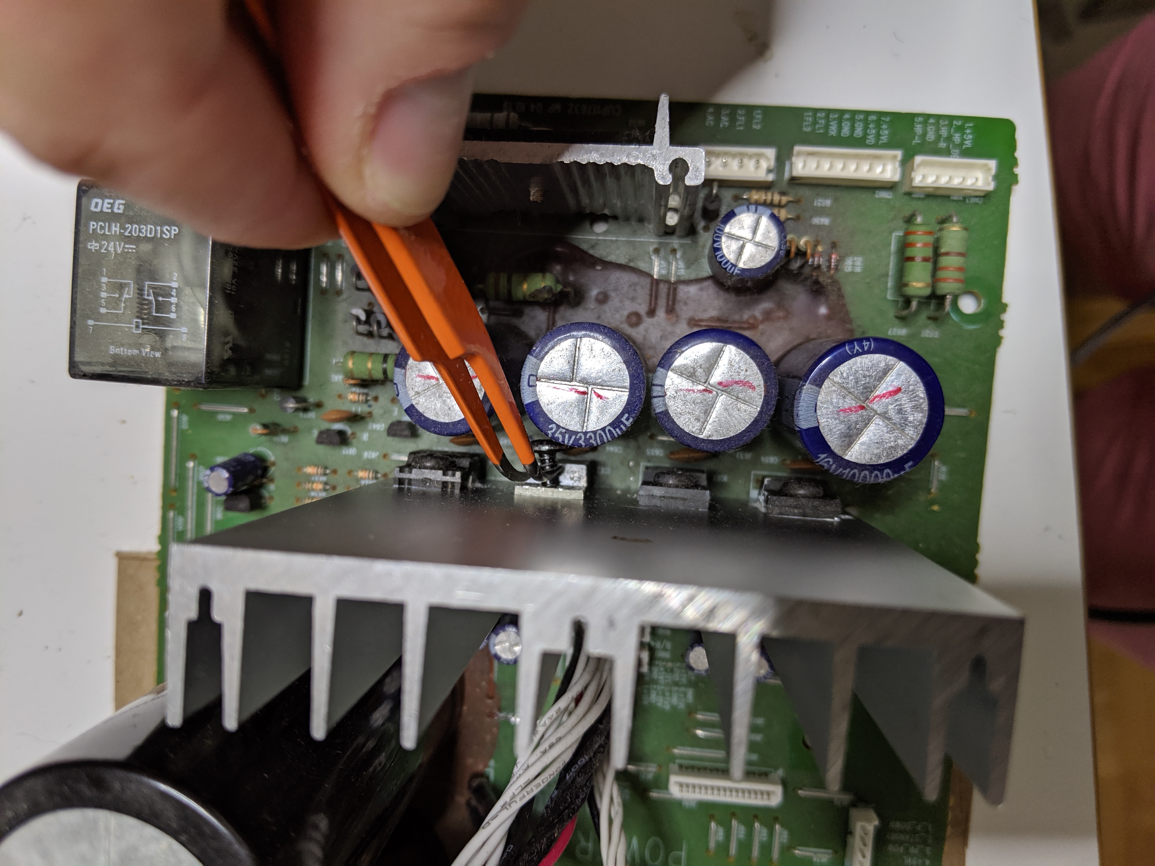
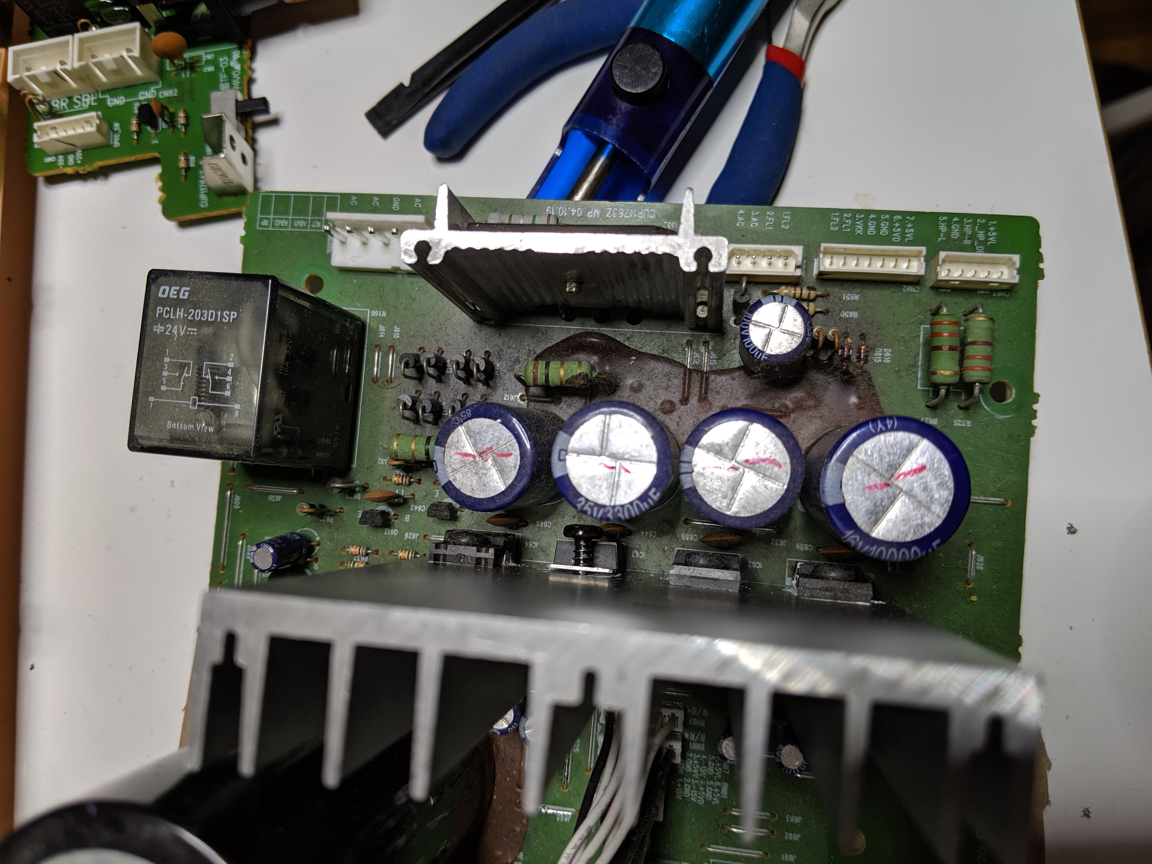
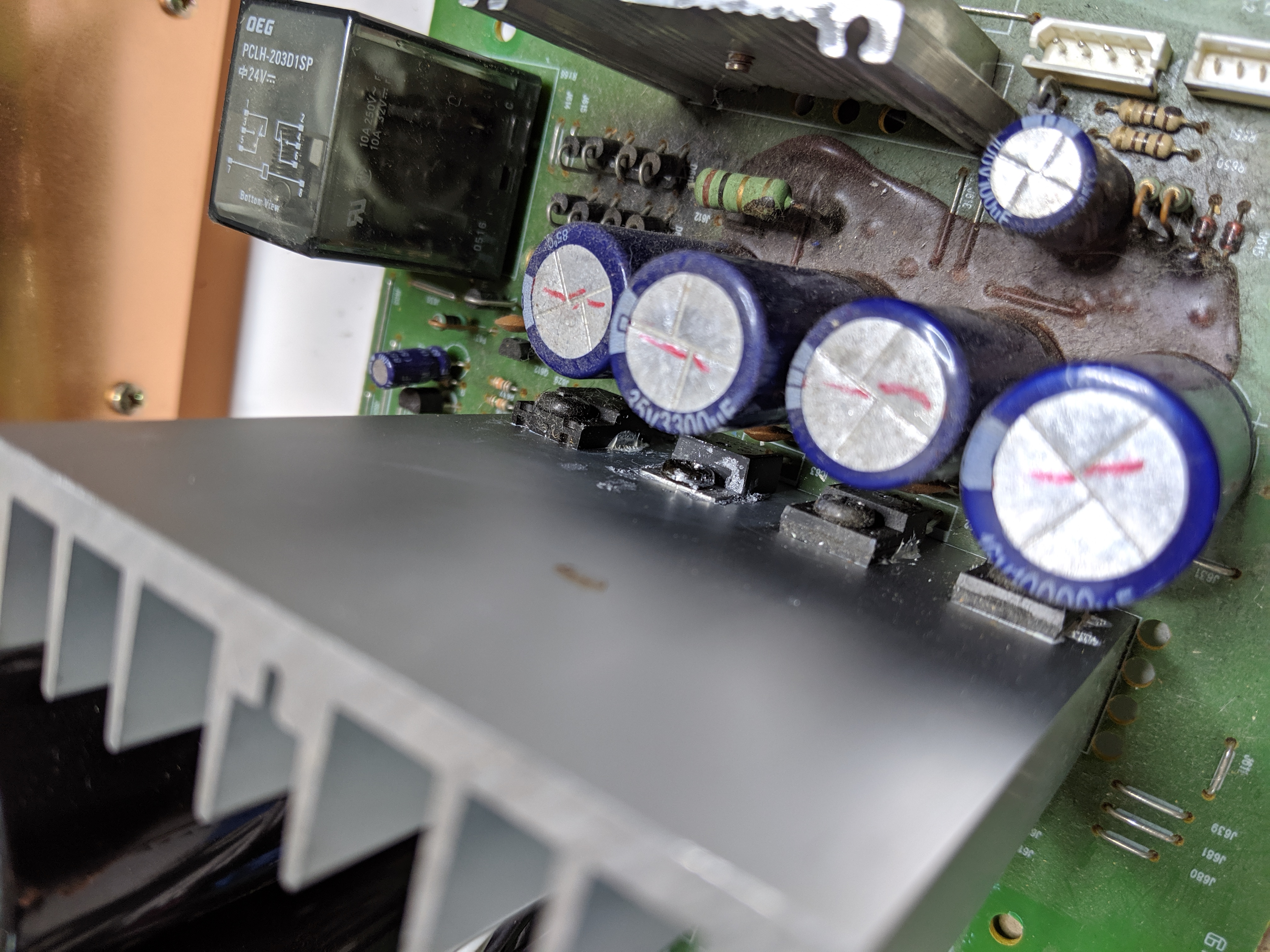
IC63 is bolted to a big heatsink and directly in front are 4 huge capacitors plus a huge rectifier also bolted to a big heatsink so it’s nearly impossible to remove it. What DFM (Design For Manufacturing) troll decided this was a good idea? Was this done specifically to prevent repair? But wait; things are about to get much more difficult!
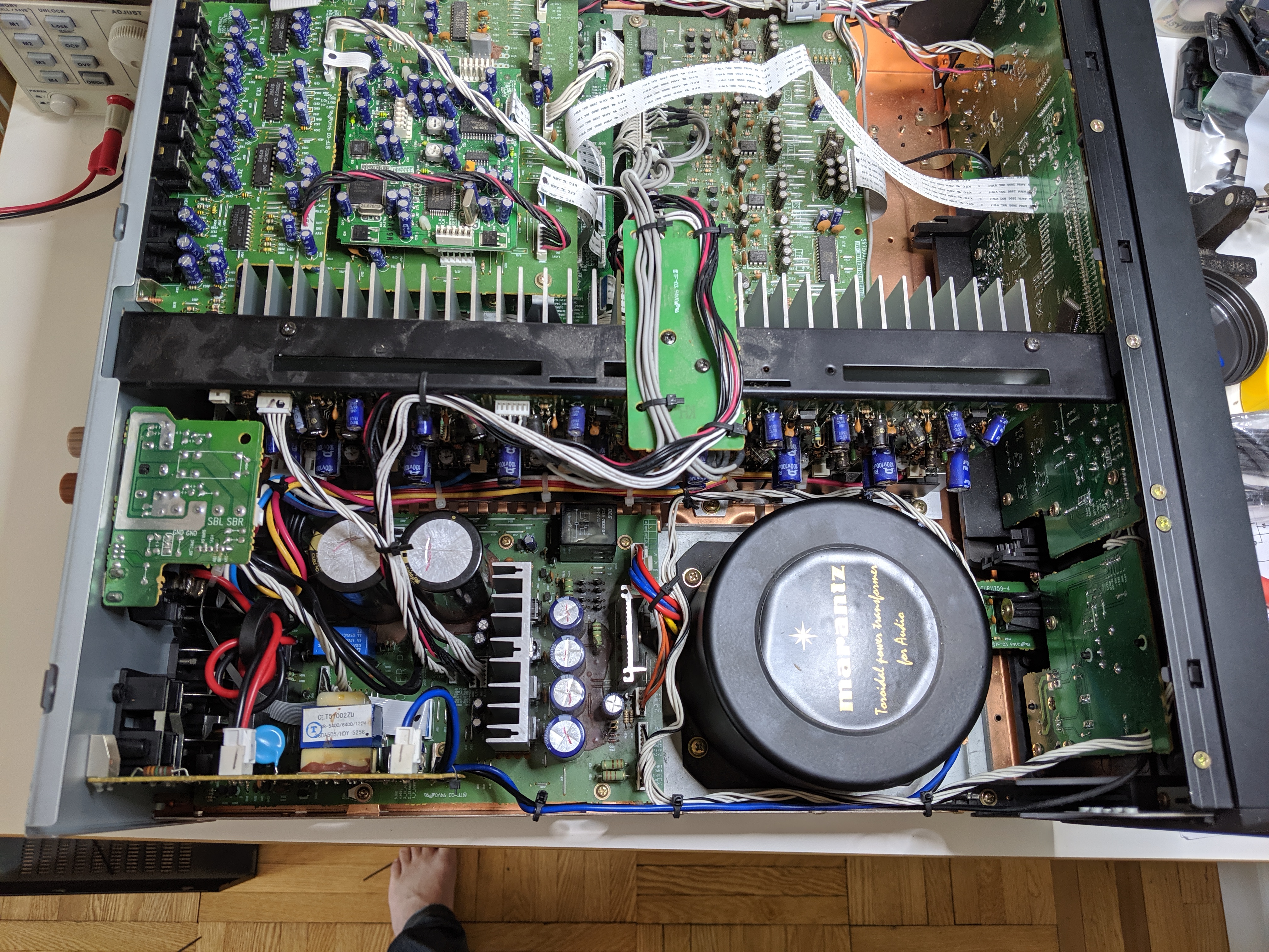
To get the power PCB out of the enclosure, we have to:
- Remove the main transformer and disconnect its 3 cables.
- Disconnect a front panel cable.
- Remove the top bracket on the amplifier assembly.
- Unplug 4 cables from the amplifier board. 1 is effectively inaccessible by hand.
- Remove the surround back left/right board and disconnect its 3 cables.
- Remove 3 large screws at the bottom of the amplifier assembly, 1 of which is occluded by several components.
- Holding 2 cables out of the way, remove the amplifier assembly.
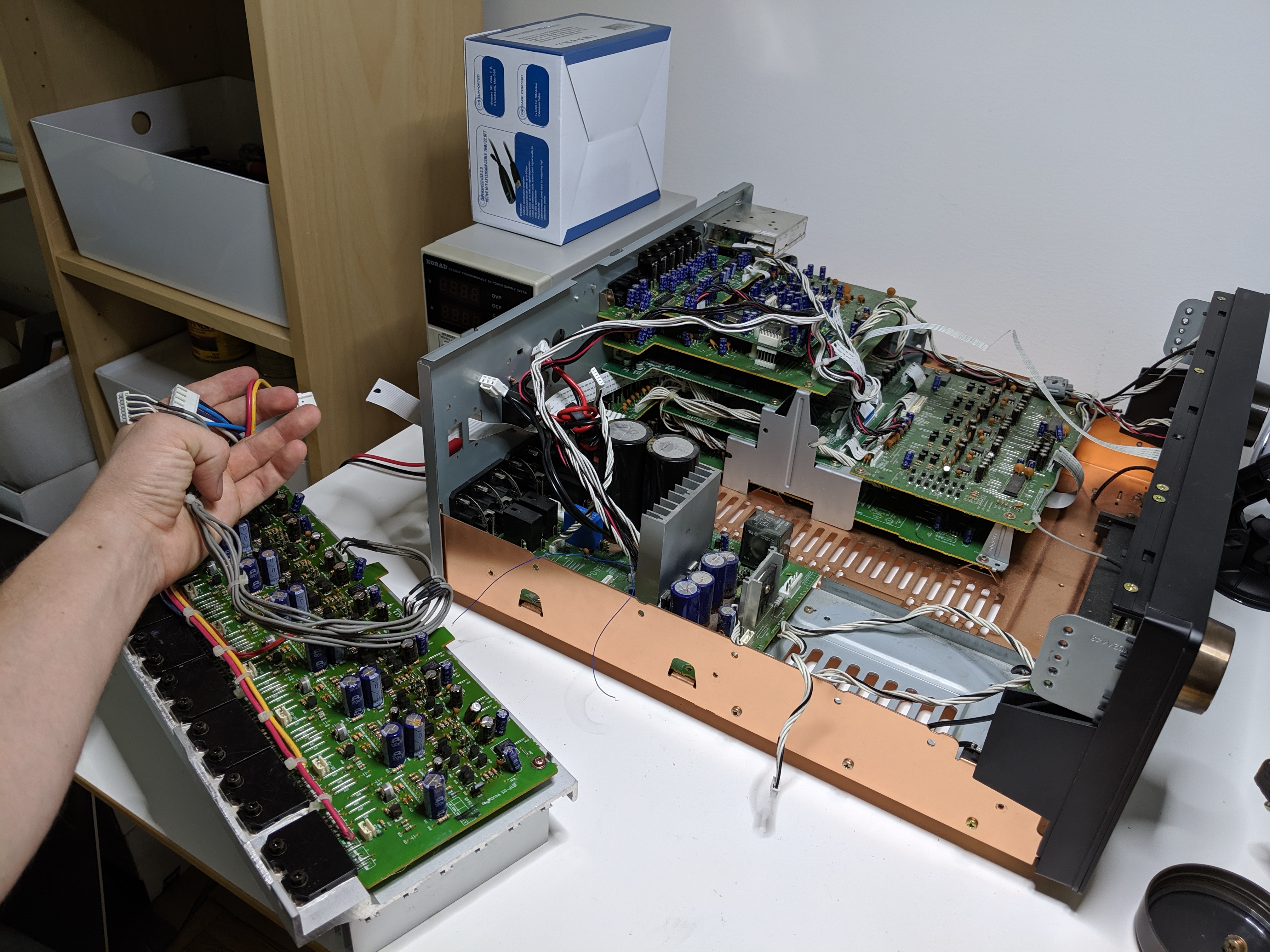
- Pull the power PCB and standby PCB assembly out like 3mm. Using a plastic stick, lever the standby PCB off the small/fragile connector it sits on. Pull the power PCB out the rest of the way, but not too far because it’s still connected by cable to boards in the other half of the enclosure.
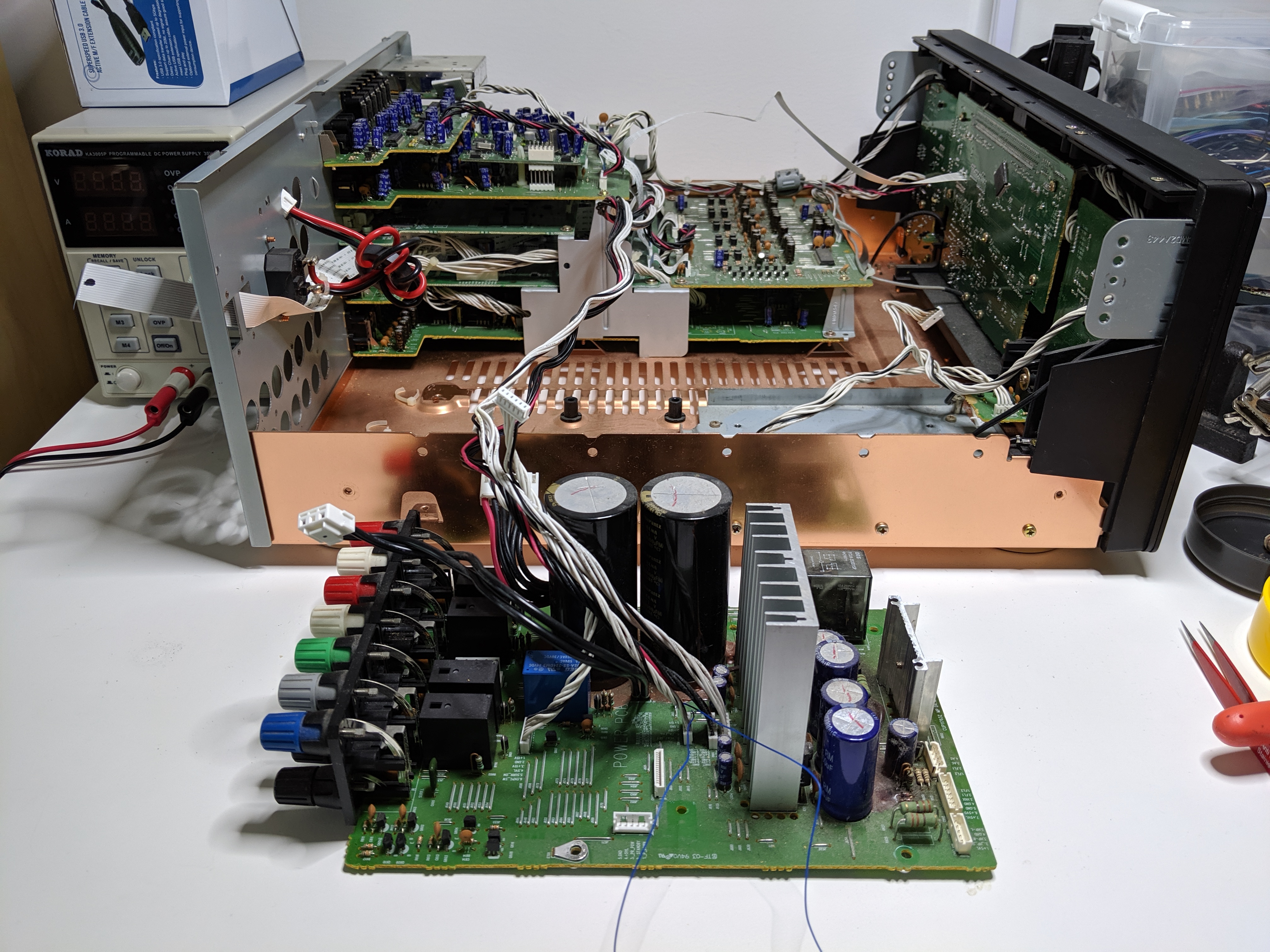
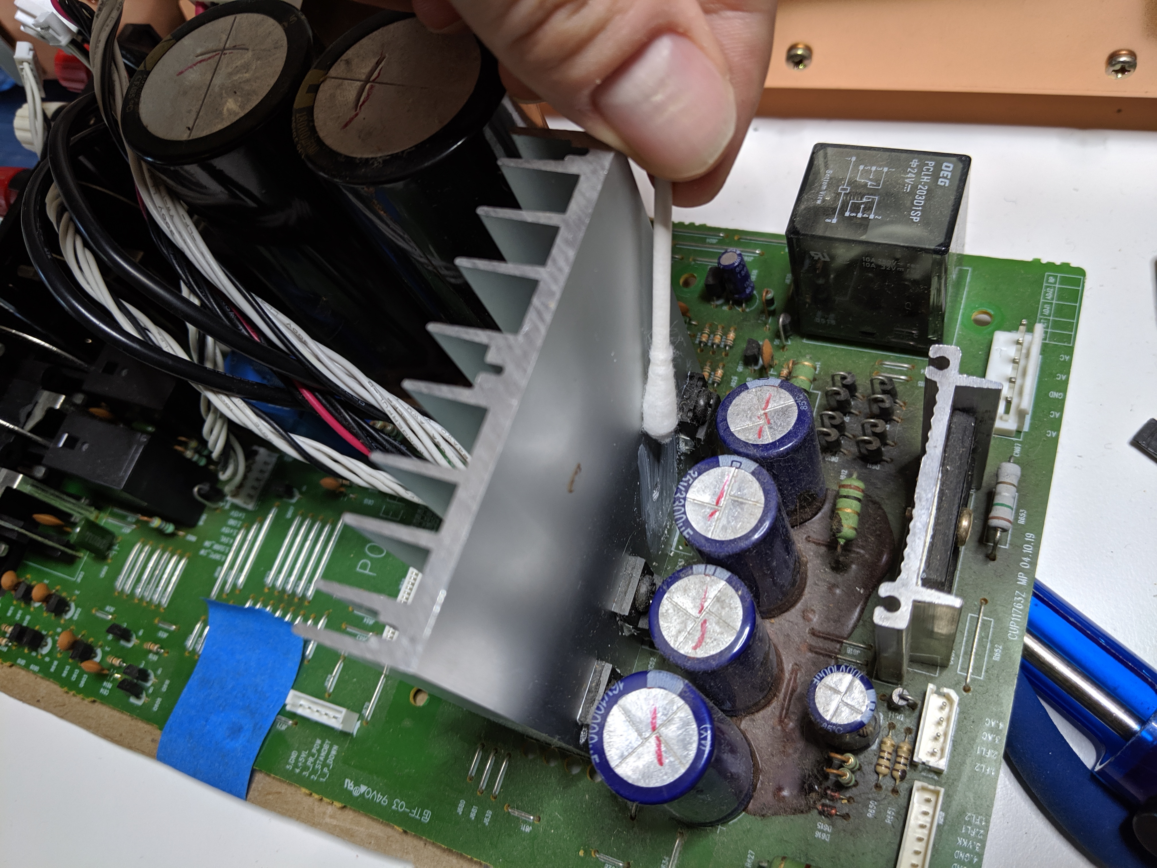
- Flip the power PCB over and put a non-conductive barrier over the huge output caps so you don’t die when you drag your arm across their terminals.
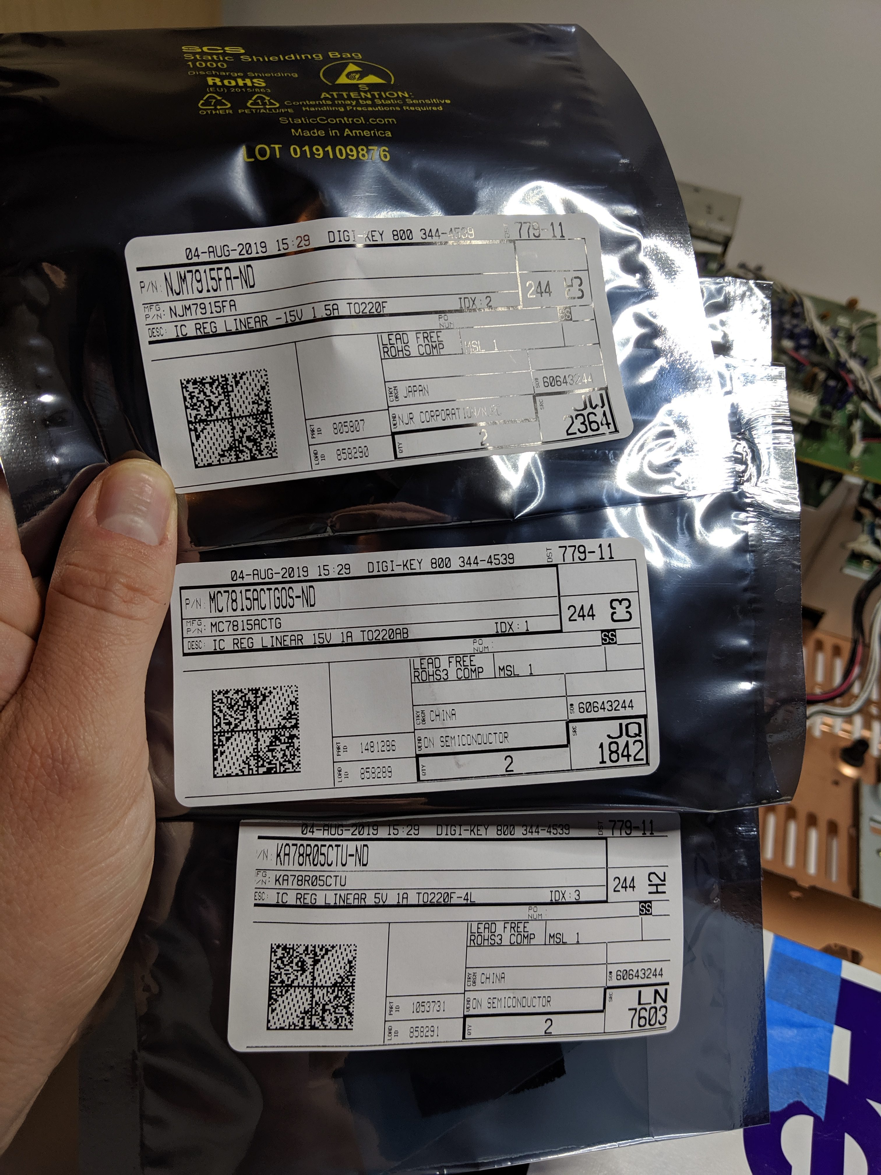
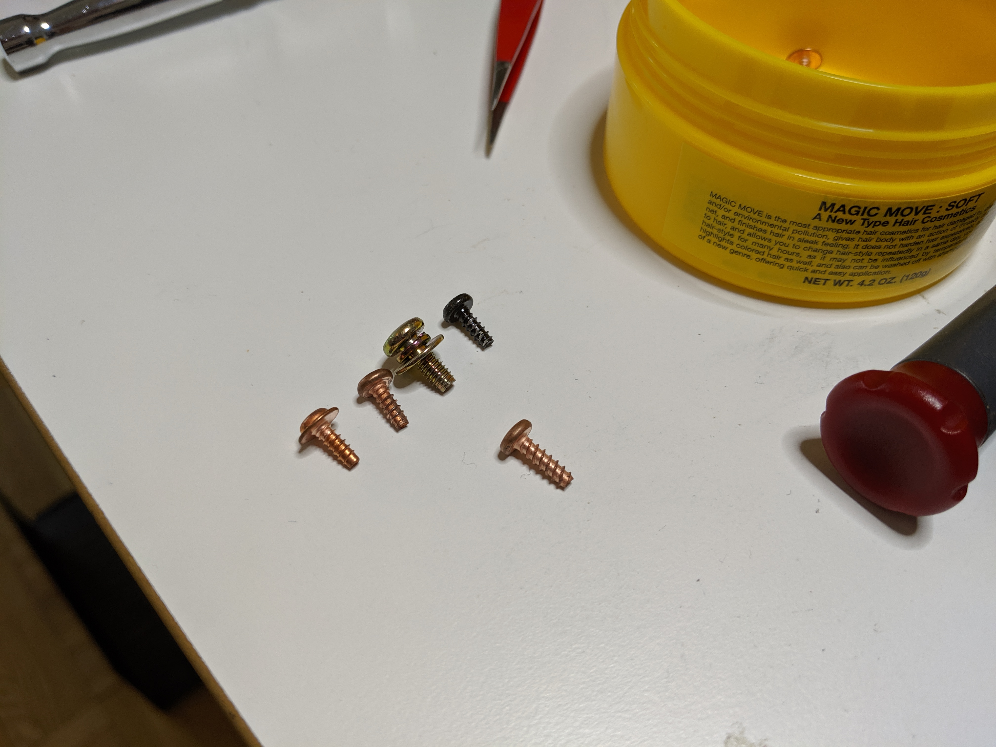
Each step also requires us to snip a plethora of zip-ties. Anyway let’s order replacements for all the LDOs in case we have another failure down the road (they’re cheap):
- Power PCB, IC63: MC7815 -> MC7815ACTG.
- Power PCB, IC64: NJM7915FA.
- Power PCB, IC61: KIA278R05PI -> KA78R05CTU
- Power PCB, IC62: KIA378R05PI -> KA78R05CTU
- Standby PCB, IC85: NJM78M05.
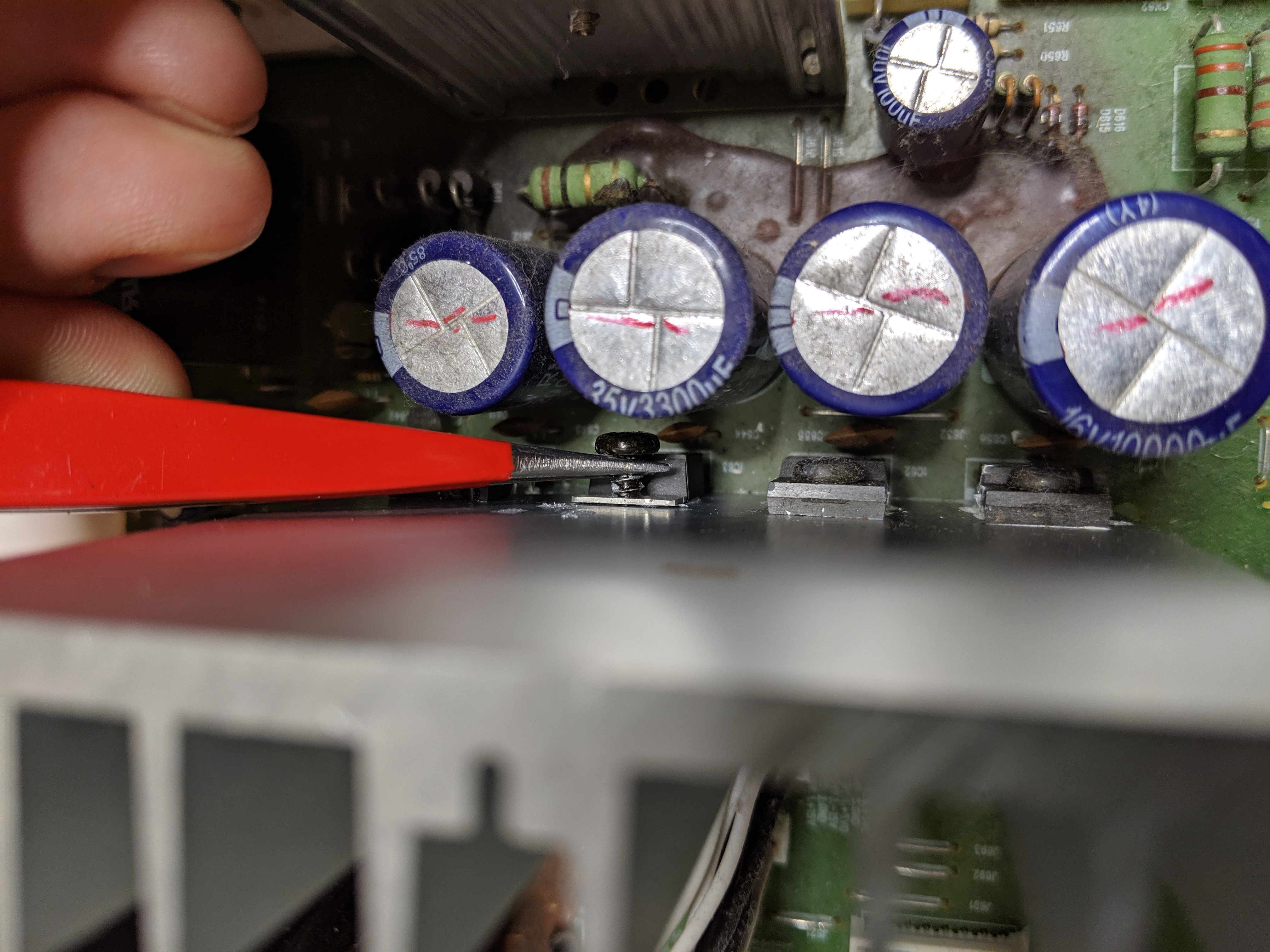
To save a ton of effort, I attempt unscrewing the heatsink bolt with a pair of pliers.
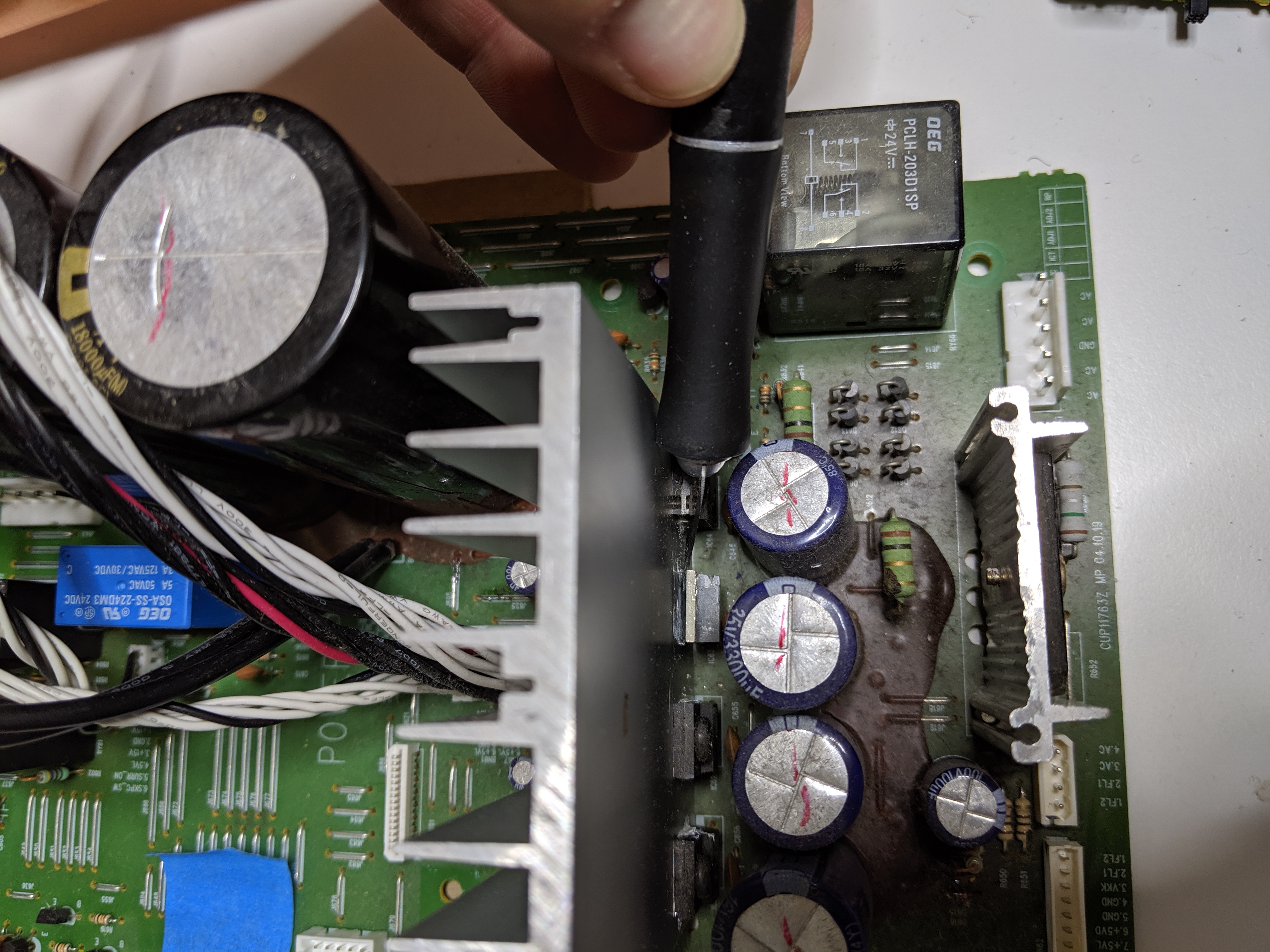
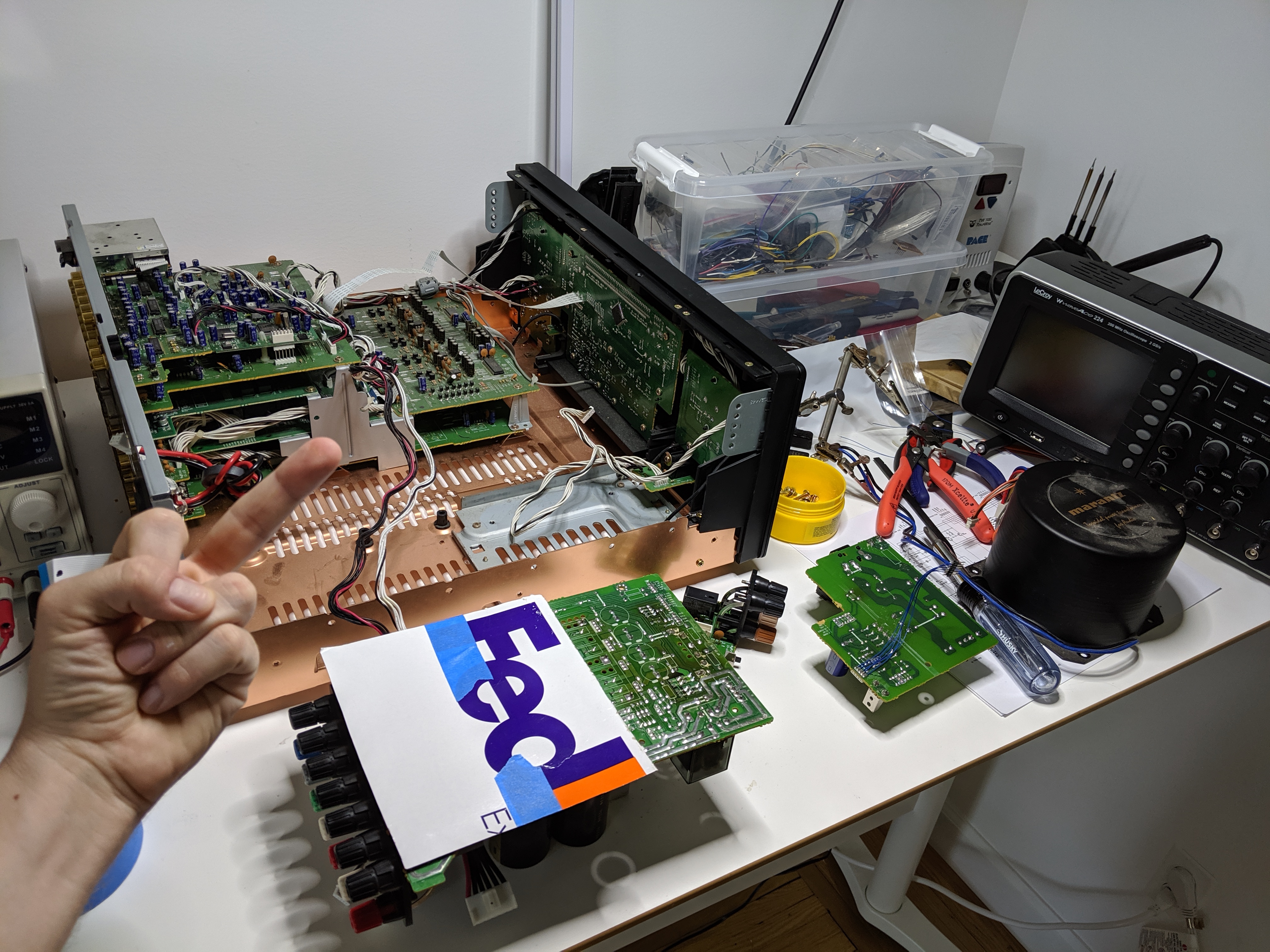
Aw yea. Let’s toss in the new part and see what happens.
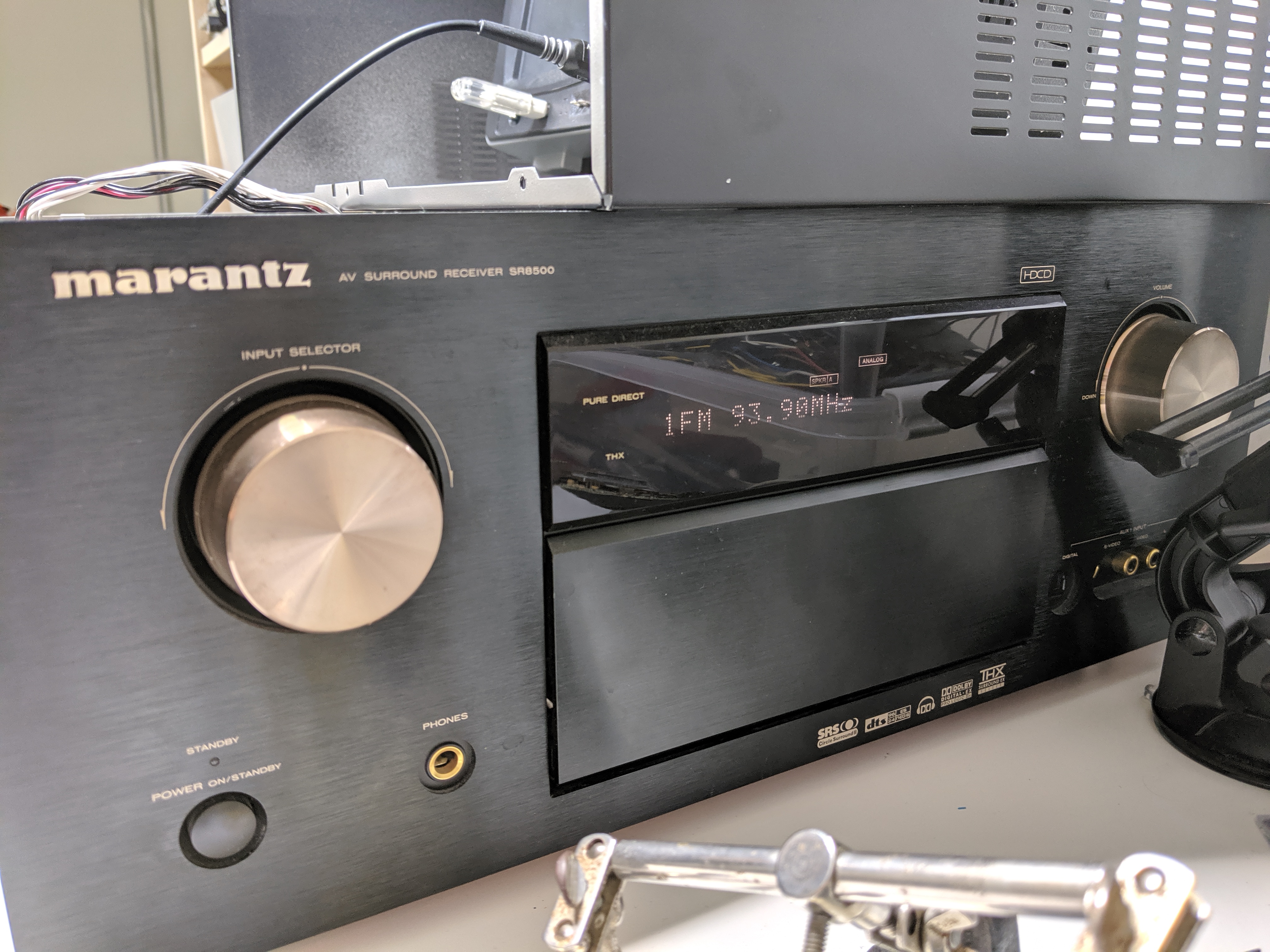
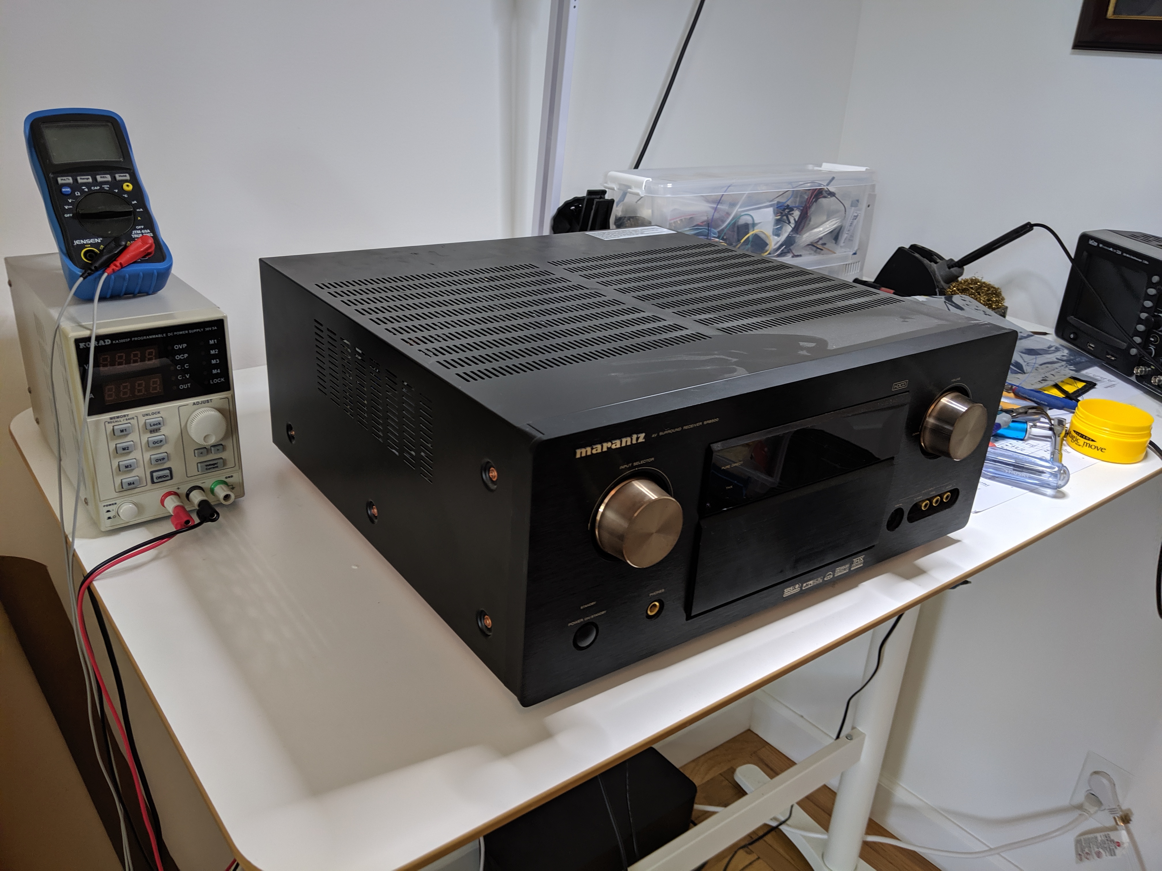
Aw yea, now let’s put everything back together!
Moral of this story
No matter how huge the task, no matter how insurmountable your fear – if you can take apart a Marantz product and remember where all the screws go, you can do literally anything.
Gallery
https://photos.app.goo.gl/NBzbBXMfUrR8PZFQ7
Resources
- http://larrynz911.blogspot.com/2012/02/marantz-sr7500.html
- https://www.avsforum.com/forum/90-receivers-amps-processors/604758-marantz-sr7500-protect-problems-amp-shutting-off.html
- https://www.youtube.com/watch?v=vA5il0m_has
- https://www.manualslib.com/manual/701768/Marantz-Sr7500-A1b.html#product-SR8500
Hi mine recently had a red light blinking. Then it stopped after a while m. Now there is no sign of life from the amp. No reaction when the power button is pushed. Could it be the same trouble like yours ?
It depends on the model I think. Mine had no blinking red light, instead it showed an error on the display then went back into standby.
Can you find schematics for your model?
I had the same symptoms. When I applied 15 volts it came up. I bought two compatible regulators from Digi-Key (the original number is out of production). The first brought the unit up but later “Check POW5” returned. The second failed also. It seems they are not compatible after all. But applying 15 volts does work so I bought a 15 volt power supply from Digi-Key and we are working but something else went wrong and there is no display and goes back into Standby. I guess I am getting Atmos whether I want it or not.
Hi mr Anders, I really enjoyed this page! Is your receiver still working? I use the cheaper brother of this Marantz (SR7500) which shares most of the boards with the SR8500. Therefore I have a question I’d like to ask you. How is the frequency responds of the SR8500? I ask you this because I miss something in the sound of the SR7500 namely the (extreme) low frequencies. My SR7500 is configured in stereo mode as amplifier only using the 7.1 channel input/setting. Two channels of the amp are being used for 2 full range speakers and two channels are being used to drive 2 passive subs and the latter is were the problem lies. I hear bass alright, which sounds full (like nothing is missing) but I completely miss the extremely low frequencies of certain songs/compositions. I know these low frequencies exist in these tracks because my former amplifier had no problems producing them using the same speakers/subs setup. Could it be that the condensators on the power PCB are dried out and lost too much of it’s value? Please let me know what you think if you find the time to check it yourself and answer. I already looked for new 18000 mfd Elna’s but they don’t come cheap so I want to be sure if it’s not just a limitation of the design of this amplifier which sounds very good for the rest. Oh, the reason I asked if the SR8500 is still working because I think the defect you repaired was caused by overheating. IMHO receivers of more than 100 watts being too packed with heat producing (video) boards really need active cooling. For an 120W amplifier the heat-sink is a bit too small in order to leave room for the other components. Whats even worse is that they place the amplifier PCB vertical in receivers in order to safe a lot of space. The horror begins when you screw this PCB against the heat sink. It simply does not belong there. That’s why this PCB colors brown in a few years in every receiver. When you place the receiver itself in a cupboard too small (not leaving enough room around the amplifier for cooling) the power PCB/amp PCB will overheat for sure. That’s why I asked if it’s still working. Placing a big low rpm fan on top of the receiver that sucks the hot air out of it does wonders. So that’s my suggestion for your receiver; Moving it out of the cupboard and cooling it actively in the summer. It needs it because of the design flaw I pointed at. As far as I know only Onkyo uses active cooling in their bigger receivers but that’s not a luxury at all.
Hi Arend,
Unfortunately I had to throw away my SR8500 when it began failing again for reasons I was unable to identify – take a look at Marantz SR8500 Repair – Part 2. Regarding the frequency response, I don’t know what the specs are between the SR7500 and SR8500, but dried capacitors could cause higher frequency content to enter the input chain. I’m not sure how dried caps might behave on the output, I’m more of a digital guy. =]
I 1000% agree with your ideas about cooling. A low-speed fan should add zero noise to a theater and triple the lifespan of an amplifier.
Update: I measured the startup time of your SR8500 and mine SR7500 thanks to the video you posted on you-tube. It’s 7:33 for the SR8500 vs 8:18 seconds for the SR7500. I think the difference between them is caused by the bigger transformer in the SR8500. Therefore I conclude that the big Elco’s are in comparable shape. So my question is can a SR8500 produce extremely low frequencies because the SR7500 just doesn’t which I find a bit disappointing for an amp that’s THX certified. Anyway, let me know and big tumbs up for your repairing skills.
I’m so glad the video helped! I wish I had an answer for you, maybe visit https://www.avforums.com/forums/ and ask your question there.
I have a sr8500 all rail voltages are close. No display
I can put audio voltage in at amp board input cn24 and I get audio out left and right front speakers. Any ideas.
Hi Dennis,
Are you able to switch inputs? Or control the system in some way to prove the system controller is working?
The receiver has a VFD display which requires higher voltage to drive it, so it’s possible the display’s HV power supply display is dead and thus you can’t see anything. If you’re able to control the system, the display might be the problem and you can look to eBay for a replacement.
Good luck!