I recently got a pile of “J5019” USB battery charger-booster boards from AliExpress, and decided to apply one of them to a work project. We had a high-detail, light-up demonstrator of our product made that looked really nice. It even had a USB “charging circuit” for the light-up electronics. Unfortunately the batteries went flat within about 30 minutes even when it wasn’t being used.
So I looked inside. I’ll give them credit – electronics are generally outside of a design firm’s expertise, and the concept did work. I’m kind of amazed it did considering there was absolutely no battery charging circuit to be found. The USB port was wired to an LDO feeding the LED controller board, the 2 LiPo battery packs, and the LED strips.
Issues
- LiPo batteries have a charging profile, and if not charged per that profile bad things happen like barely hold charge or explode.
- The tiny LDO gets extremely hot trying to deliver current to everything.
- The LED strips require 5v to work properly, yet the maximum voltage the batteries could provide is 4.2v.
- The LED strips have logic running inside each LED whenever it’s powered, so it’s always drawing a large amount of current.
Solution
- Add a battery charger + booster.
- Makes the battery actually work.
- Makes the LED strip actually work.
- Cut a trace in the booster section of the battery charger + booster.
- Allows the LED controller to disable the booster when the LED strips are not in use.
- Add a load switch.
- Allows the LED controller to cut power to the LED strips when they’re not in use. A booster not boosting simply passes battery voltage directly to the load.
- Recreate the LED controller and use sleep modes whenever the LED colors are not changing.
Notes
- When I first hooked in this charger + booster circuit, the booster would continuously start and stop trying to feed the load as the battery was being charged, siphoning charge to the battery.
- We can use the ADC and internal 2.56v reference to periodically sample the raw and boosted battery voltage.
- We can know when the LED controller suffers power loss using the POR flag in the MCUSR register, and refuse to enable the booster until the raw battery charge is above a threshold.
Required Items
- LiPo Battery Charger + Booster
- Load Switch
- Arduino Pro Micro
- LED Controller Firmware built using the Arduino platform
- DuPont-style jumper wires and hot glue
Battery Charger + Booster
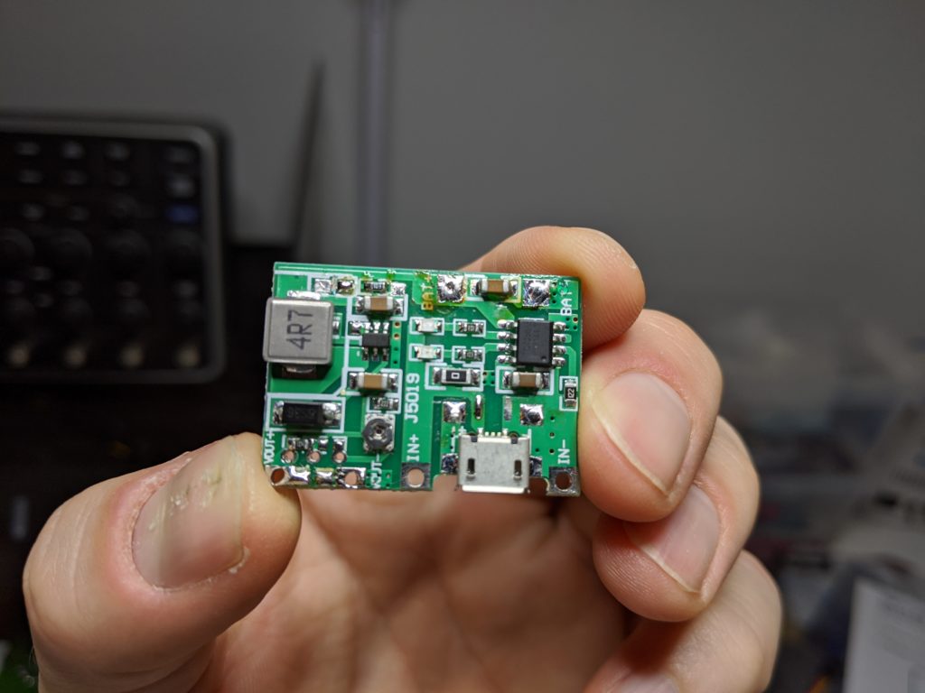
Looking at where the PCB traces are going, the booster circuit looks like it was driven by an MT3608, a common Asian IC.
Looking closer, it appears the PCB was designed with extra pads in case someone wanted to default to “not boosting” upon power-up. We can use this to our advantage by installing a pulldown resistor and attaching a control wire to the Arduino, boosting only when we want to. Further, we can tie into the “Charging” and “Charge Complete” status pins, to redirect these indications to the LED strip the user can actually see.
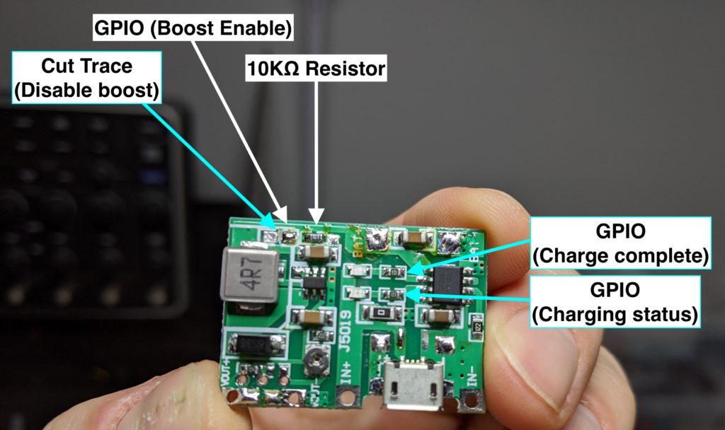
NOTE: ADJUST THE BOOST VOLTAGE WITH A MULTIMETER BEFORE ATTACHING TO CIRCUITRY. These boards can boost up to 26v, and we want no more than 5.5v. They arrive boosting to around 7v IIRC.
Anyway, I hooked up:
- The 3 control wires to the Arduino
- Both LiPo cells (in parallel) to the BAT +/- terminals
- The USB port to the IN +/- terminals
- A small power bus to the VOUT +/- terminals
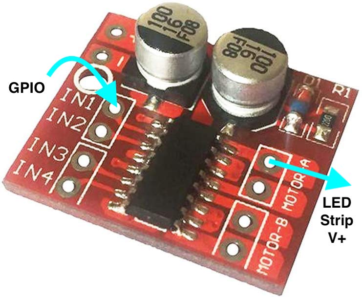
Load Switch
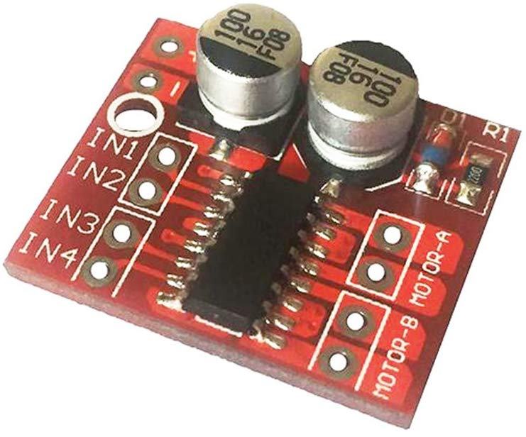
I had an extra DC motor driver laying around I could use to gate 2A of power to something by using one of the 4 outputs to deliver the high-side (5v) supply to the LED strip. I connect an Arduino GPIO to IN1 on the motor driver, and MOTOR-A1 to V+ on the LED strip. GND on the LED strip is connected to the main power bus GND like all other GND connections.
Final product
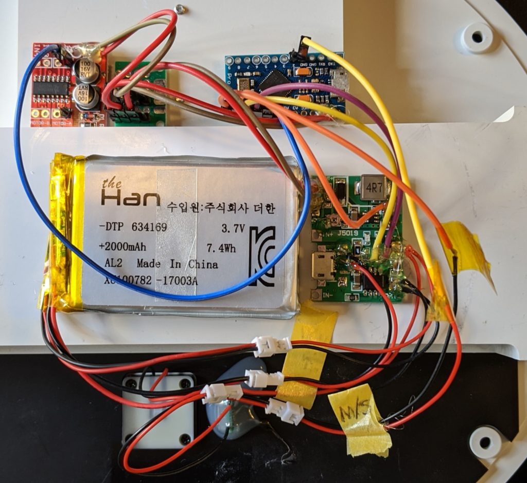
Note: the LED strip connections (V+, GND, data) are not connected in the above image.
The Arduino firmware linked above will show you the GPIO pin connections and how it senses whether the battery is not charging, charging and fully charged. The firmware makes use of the Interrupt-On-Change functions of GPIO on PORTB so it can go into low-power sleep when the LEDs are off, then wake up when the user button or charging status changes.
Right now charging status display functions are not defined but there are events in the code you can fill in. The code uses the FastLED library to easily change the LED colors and the LowPower library to enter sleep mode.
Gallery
https://photos.app.goo.gl/STmnuojRioABLaCZ9
Resources
- https://circuitdigest.com/microcontroller-projects/arduino-sleep-modes-and-how-to-use-them-to-reduce-power-consumption
- https://hackaday.com/2019/01/27/reworking-mt3608-boost-converters-for-lower-idle-current-draw/
- https://forum.arduino.cc/index.php?topic=411851.0
- https://github.com/rocketscream/Low-Power
- https://forum.arduino.cc/index.php?topic=535764.0
- https://www.reddit.com/r/FastLED/comments/b8qlbe/newbie_help_simple_fadeblend_code/
- https://github.com/marmilicious/FastLED_examples/blob/master/blend_to_target_color.ino
- https://forum.arduino.cc/index.php?topic=606431.0
- https://github.com/arduino/ArduinoCore-samd/issues/103