Abstract
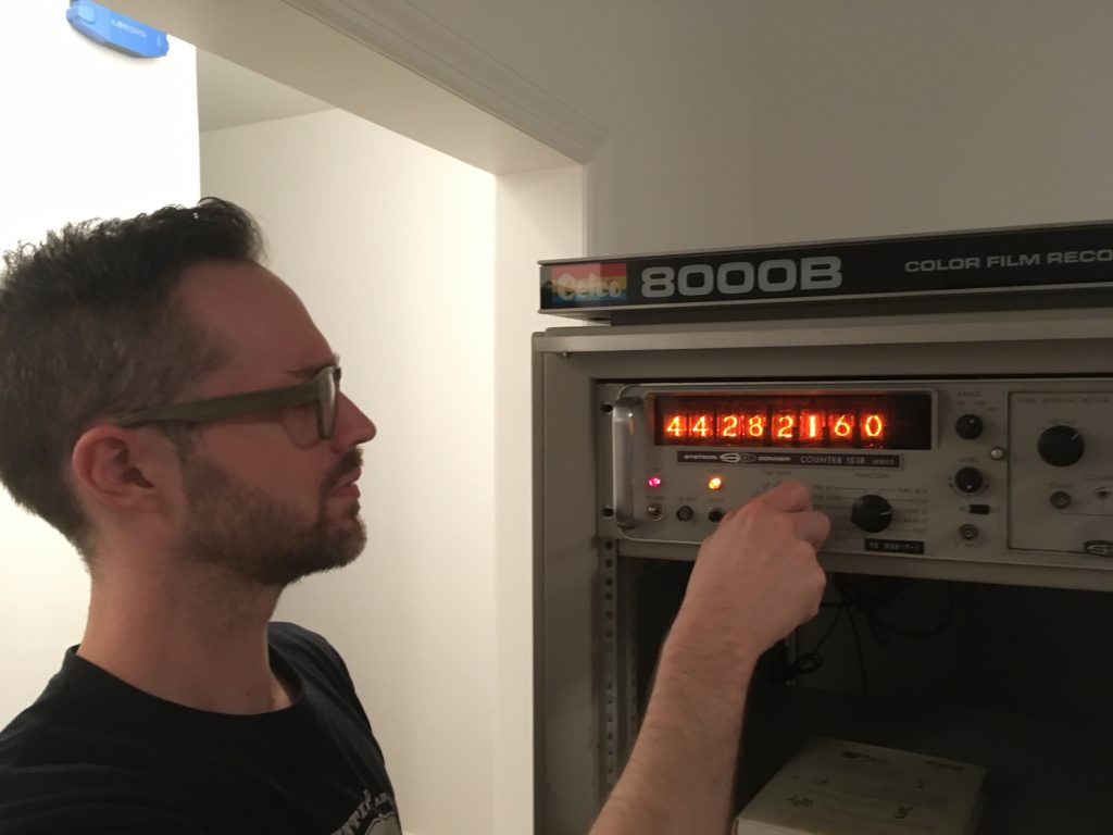
An old Systron-Donner counter with nixie tube indicators repurposed as an internet-connected clock.
What it’s made of
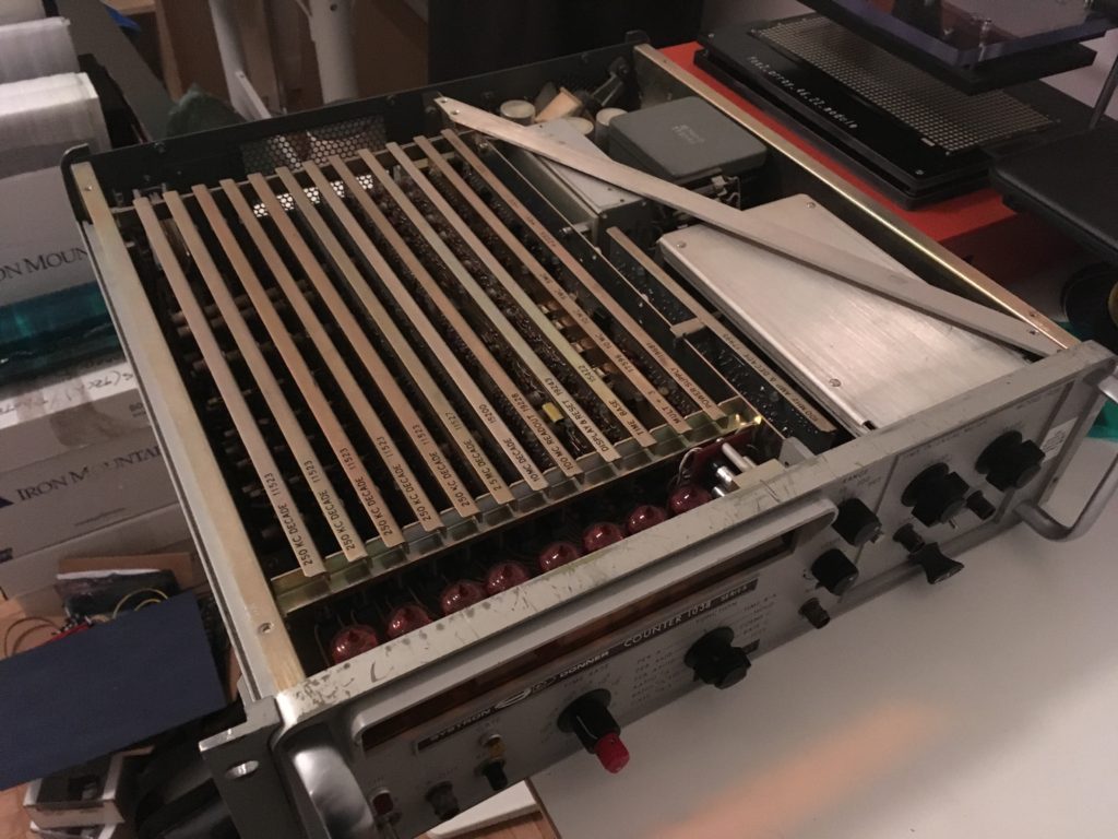
- Systron-Donner model 1038 counter
- ESP32 development board
- Software written in C
- Custom PCB designed in EAGLE
- High voltage nixie tube power supply
- 12v AC-DC power supply
How it works
The internet connection (and time, if set manually) is configured through a simple terminal interface. From here, an SNTP client running on the ESP32 fetches the current time.
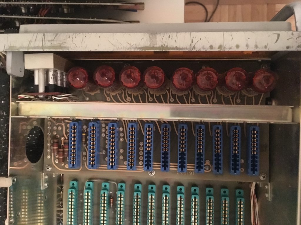
Concurrently the ESP32 sets I/O pins to illuminate filaments in the nixie tubes according to the current time. The ESP32’s I/O pins connect to the high-voltage sink drivers already inside the counter.
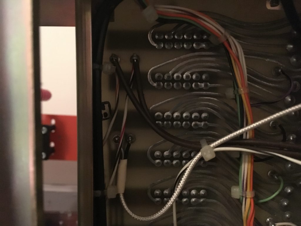
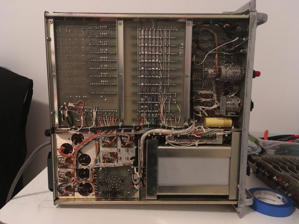
I inserted jumpers between the parts inside the counter required to drive the tubes/indicators and the rest of the apparatus. This way running the clock didn’t take like 150W of power and howl like the winds of Kilimanjaro. If I ever wanted to use the counter in it’s original form though, I could by replacing the jumpers.
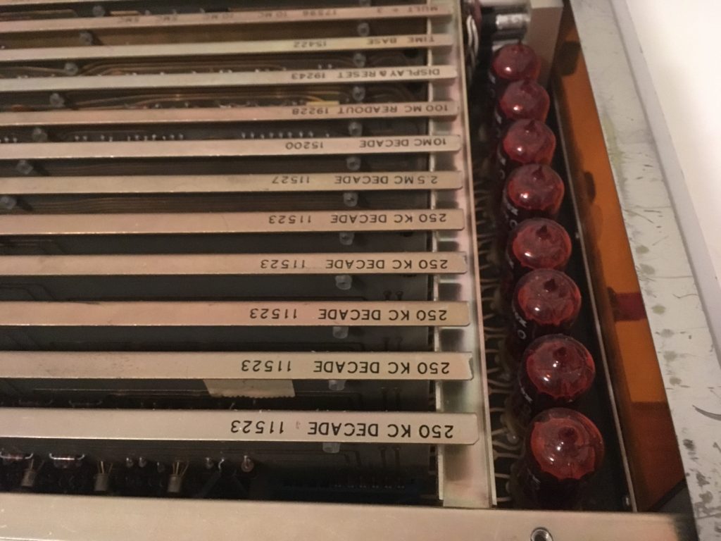
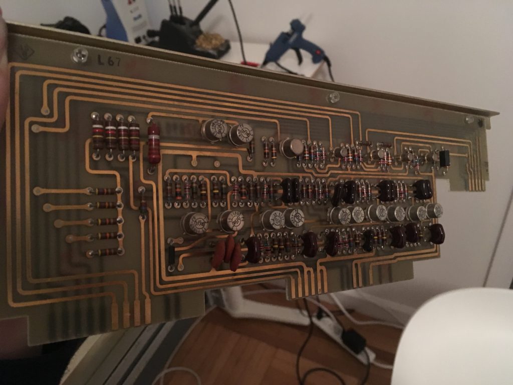
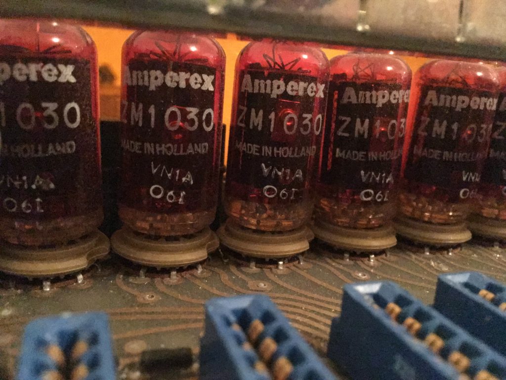
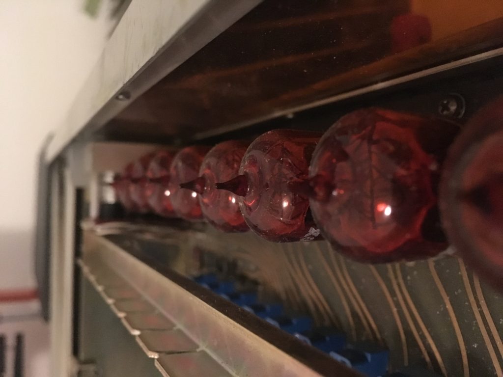
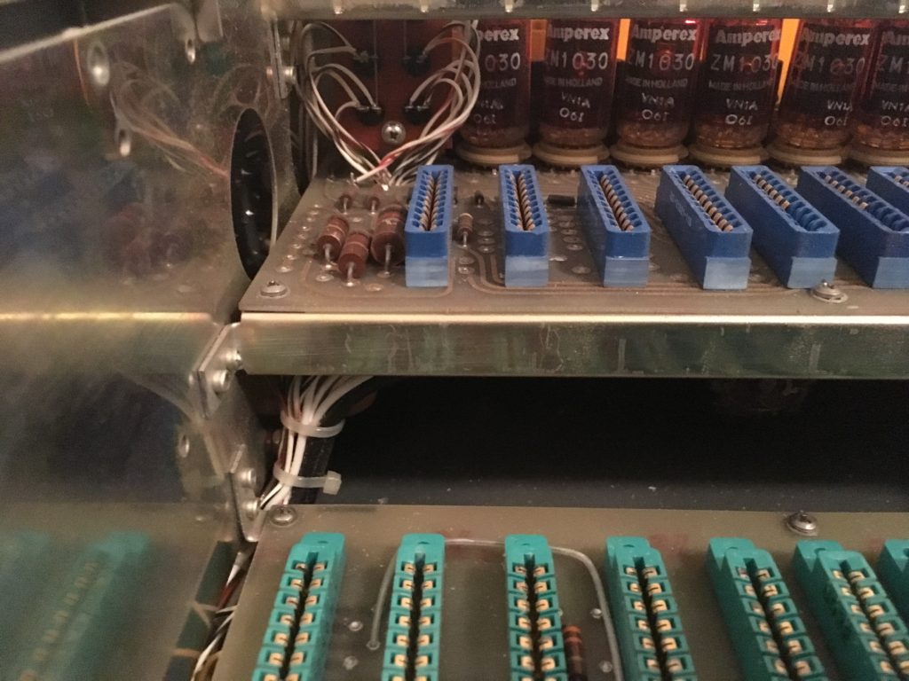
JUST KIDDING there are no solid-state drivers anywhere in this thing, it’s all diode-transistor logic so I’ll unfortunately have to insert my own driver circuit between the counter and the nixie tubes. Given the physical placement of the tubes at the proper height for readability and the insane rats nest of wiring and traces in this machine, I’ll be cutting traces to the existing tube sockets and placing a new board that drives those traces. High-voltage insulation will be needed.
Also these ZM1030 tubes are dual-anode which makes the driver circuit more complicated with three necessary supplies to prevent ghosting. Doing the math, I can get by with using one high voltage supply (200v) and dividing the voltage down where necessary. This is inefficient, but if I were to energize all tubes at once I’d be throwing away nW which isn’t a problem thermally or financially. Turns out, n = ~10W so I’ll be putting in those efficient supplies after all.
I chose the Microchip HV5122 sink driver to control the tubes. The numerals are pulled up to 200V when idle, then get pulled down to 0V to light up. The anode P-FET gates are also pulled up to 200V when idle then get pulled down to ~195V when anode current is called for. If we were to pull the gate to 0V, Vgs would be 200V – about 10x what the part can handle. The screen is always powered at 50V.
Links
- https://threeneurons.wordpress.com/nixie-power-supply/
- http://www.dos4ever.com/nixie1/nixie1.html
- https://www.radiomuseum.org/tubes/tube_zm1030.html
- http://a.co/iJqJZcS
- http://a.co/j2j5Pnr
- http://a.co/07LQ06z
- https://github.com/espressif/esp-idf/blob/master/examples/protocols/sntp/main/sntp_example_main.c
- https://github.com/espressif/arduino-esp32/issues/437
- https://hackaday.com/2017/08/17/secret-serial-port-for-arduinoesp32/
- https://networkengineering.stackexchange.com/questions/23761/how-to-get-local-time-from-internet
- https://stackoverflow.com/questions/14476314/using-printf-with-two-uarts
- https://hackaday.io/project/27899-nixie-tube-power-supply/log/70130-adding-controls
- https://hackaday.io/project/27899-nixie-tube-power-supply
- https://doayee.co.uk/nixie/